|
|
|
Categories
|
|
Information
|
|
Featured Product
|
|
|
 |
|
|
There are currently no product reviews.
 ;
In a word AWESOME.
I never expected the quality and abundant content that I got with this manual. Everything you'd ever want to know from a service perspective is found in this manual, along with... as a bonus, operating instructions on how to use the unit. WOW. Very impressed with the quality of the manual. You won't be disappointed if you're looking for the EVS900 service manual.
;
I thank Owen-Manuals.com for the wonderful service rendered to me, and this manual which I purchased helped me a lot in servicing my Denon System, which was lying in a dead state.
Thanks Owner-Manual.com
;
I purchased this manual to repair my Teac set and with the support of this manual I rectified the problem.
Thanks Owner-Manuals.com
;
Excellent service manual, i didn't believe i could find it for such old product, it is very explanatory, managed to fix the disk player!!!
 ;
Nice manual. Clear copy and very rare, to boot. Great price, too!
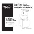
Amplifier/Subwoofer
BU-80/BU-80EHTS-10
BU-80/HTS-10 INTEGRATED CIRCUIT/TRANSISTORS DIAGRAM
S53AM/S64AMI - Power Amp module SAFETY PART BU-80 and HTS-10 rev �A, B� ONL Y
+6V 15 16 V+ 17 18 O/P 19 20 V21 22 +15V SD FR I/P GND -15V 23 24 25 26 27 28 1 2 3 4 5 6 7 8 9 10 11 12 13 14 +15V SD FR I/P GND -15V
If the new Amp Module has larger mounting hole(s) in the case, and the stock screws no longer will fit, and screws of the proper type cannot be obtained locally order:
GND S/D
+6V
NOTE: THE FOLLOWING PROCEDURES MUST BE FOLLOWED WHEN INSTALLING NEW AMP MODULES: FAILURE TO FOLLOW ONE OR MORE OF THESE STEPS MAY RESULT IN THE INSTANT DESTRUCTION OF THE MODULE WHEN POWERED UP.
00228
LIMIT 6V
V+
O/P
1) Align white indent marker on Amp Module with indent marker on main PCB; alternately position of label on the top of the module; incorrectly replacing the Module 1800 in the PCB slot will result in its destruction. 2) All AC powered test instruments (meters, oscilloscopes, etc.) must have a floating ground, i.e. be connected to an isolation transformer. 3) Align and position the Amp Module before soldering. 4) Attach the amp Module with the mounting screws before soldering or powering up. 5) Use only rosin-core or non-acid core solder; thoroughly de-flux the surfaces after soldering.
+15V VV-
V-
(2) part# 60301S (screws) (2) part# 60301N (nuts) QUAD OP AMP, LM324, TL074 U1, IC101 BU-80E & HTS-10 rev �C� ONLY
15 14 13 12 11 10 9 8 7 6 5 4 3 2 1
TRANS, NPN MPS A13 (Darl) Q1
3 COLLECTOR 2 BASE 1 EMITTER
CN101
MOSFET TRANS IRF530 Q2, 3
TRANS, PNP, 2SA1015 Q101, 104, 105
TRANS, NPN, KSP113 2SC1815 Q102, 103
IC 74HC14N HEX SCHMITT TRIGGER INVERTER U2, 3
00370
V+
V+
V+
O/P
PWR MODULE
V-
IN
-15V
FB
JFET DUAL OPAMP LF353N U1
VCC 14
1. DRAIN 2. GATE 3. SOURCE
A6 13
Y6 12
A5 11
Y6 10
A4 9
Y4 8
OUT1
1 2 3 4
8 7 6 5
V
CC
IN1 (�)
OUT2
IN1 (+)
IN2 (�)
TRANS, PNP, 2N3906 MPS A56 Q2, 4, 5
TRANS, NPN, 2N5551 2N3904 Q1, 3
VEE
IN2 (+)
1 A1
1 2 3
2 3 Y1 A2
4 5 Y2 A3
6 7 Y3 GND
24
|
|
|
> |
|